J’ai décidé de construire un feux arriere qui flash en fonctionnement normal et qui s’éclaire pleinement en cas de freinage (afin d’éviter les collisions avec les copains qui suivent derrière).
Pour résumer le budget est inférieur à 10€, l’encombrement 2*3 cm et le tout alimenté par le vesc (ou pas) car la consommation (en fonction de la lampe stop biensur) est de 200mA - 5V
PART LIST :
- Digispark microcontroller (8€) https://www.amazon.fr/ANGEEK-Digispark-kickstarter-Development-ATTINY85/dp/B07WZZVXNW/ref=sr_1_3?__mk_fr_FR=ÅMÅŽÕÑ&dchild=1&keywords=digispark&qid=1587287272&s=electronics&sr=1-3
- Remote control (32€) https://fr.aliexpress.com/item/32839721232.html?spm=a2g0s.9042311.0.0.29266c37RpSkCy
- 5Volt LED Light (10-30€) : It depends if if you buy only back light or a pack.
- Resistance
- Transistor BC547
CIRCUIT : la conso est de 200mA quand la lampe est allumée, donc c’est assez pour etre alimenté par le VESC
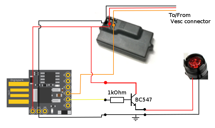
SOFTWARE : Pour l’installation de la librairie digispark ce tutorial est bien:
Installing Drivers and Programming the DigiSpark ATtiny85 dev boards - Tutorial
Pour le logiciel je me suis inspiré :
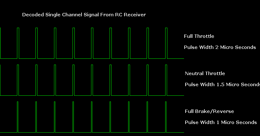
How To Read an RC Receiver With A Microcontroller - Part 1
J’ai juste modifié pour faire flasher la lampe quand le skate ne freine pas
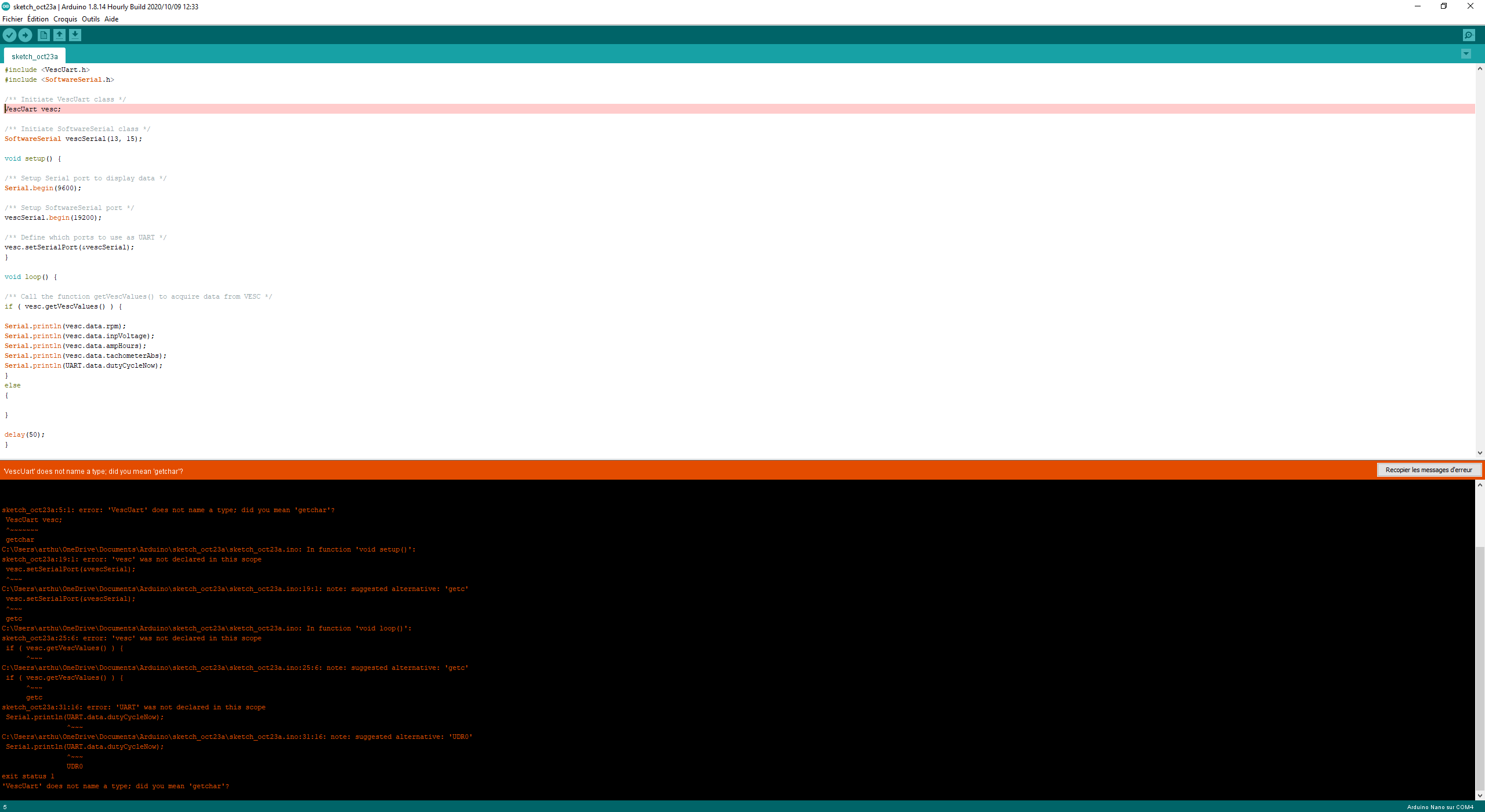
Le programme :
#define THROTTLE_SIGNAL_IN 0 // INTERRUPT 0 = DIGITAL PIN 2 - use the interrupt number in attachInterrupt #define THROTTLE_SIGNAL_IN_PIN 2 // INTERRUPT 0 = DIGITAL PIN 2 - use the PIN number in digitalRead #define BRAKE_SIGNAL_OUT 1 #define NEUTRAL_THROTTLE 1500 // this is the duration in microseconds of neutral throttle on an electric RC Car #define PERIOD_BLINK 1000 // #define DURATION_BLINK 200 //
volatile int nThrottleIn = NEUTRAL_THROTTLE; // volatile, we set this in the Interrupt and read it in loop so it must be declared volatile volatile unsigned long ulStartPeriod = 0; // set in the interrupt volatile boolean bNewThrottleSignal = false; // set in the interrupt and read in the loop volatile boolean b_ActivateBlinkBrake = true; // Active blink brake light functionality volatile boolean b_EnableBlinkBrake = false; // Brake light show brake info in priority volatile unsigned long u_Cpt_Interrupt = 0; volatile boolean b_BrakeLightValue = false;
// we could use nThrottleIn = 0 in loop instead of a separate variable, but using bNewThrottleSignal to indicate we have a new signal // is clearer for this first example
void setup() { // tell the Arduino we want the function calcInput to be called whenever INT0 (digital pin 2) changes from HIGH to LOW or LOW to HIGH // catching these changes will allow us to calculate how long the input pulse is attachInterrupt(THROTTLE_SIGNAL_IN,calcInput,CHANGE); pinMode(BRAKE_SIGNAL_OUT, OUTPUT); //Serial.begin(9600); }
void loop() { // if a new throttle signal has been measured, lets print the value to serial, if not our code could carry on with some other processing if(bNewThrottleSignal) { //Serial.println(nThrottleIn);
// set this back to false when we have finished // with nThrottleIn, while true, calcInput will not update // nThrottleIn
u_Cpt_Interrupt++;
if(nThrottleIn <NEUTRAL_THROTTLE) { //Throttle BRAKE //Disable Blink light b_EnableBlinkBrake = false;
// Full light on brake output
b_BrakeLightValue = true;
//digitalWrite(BRAKE_SIGNAL_OUT,HIGH);
} else { b_EnableBlinkBrake = true; //Throttle NOT BRAKE b_BrakeLightValue = false; //digitalWrite(BRAKE_SIGNAL_OUT,LOW); } bNewThrottleSignal = false; }
//Manage blink light if(b_ActivateBlinkBrake && b_EnableBlinkBrake) { //Interrupt normally happen every 20ms if(u_Cpt_Interrupt * 20 > PERIOD_BLINK) { b_BrakeLightValue = false; if(u_Cpt_Interrupt * 20 < PERIOD_BLINK + DURATION_BLINK ) { b_BrakeLightValue = true; } else { //Reset cpt for new cycle u_Cpt_Interrupt = 0; } } } else { //Reset cpt for new cycle u_Cpt_Interrupt = 0; }
//Manage Brake Light output if(b_BrakeLightValue) { digitalWrite(BRAKE_SIGNAL_OUT,HIGH); } else { digitalWrite(BRAKE_SIGNAL_OUT,LOW); }
// other processing … }
void calcInput() { // if the pin is high, its the start of an interrupt if(digitalRead(THROTTLE_SIGNAL_IN_PIN) == HIGH) { // get the time using micros - when our code gets really busy this will become inaccurate, but for the current application its // easy to understand and works very well ulStartPeriod = micros(); } else { // if the pin is low, its the falling edge of the pulse so now we can calculate the pulse duration by subtracting the // start time ulStartPeriod from the current time returned by micros() if(ulStartPeriod && (bNewThrottleSignal == false)) { nThrottleIn = (int)(micros() - ulStartPeriod); ulStartPeriod = 0;
  // tell loop we have a new signal on the throttle channel
  // we will not update nThrottleIn until loop sets
  // bNewThrottleSignal back to false
  bNewThrottleSignal = true;
}
} }
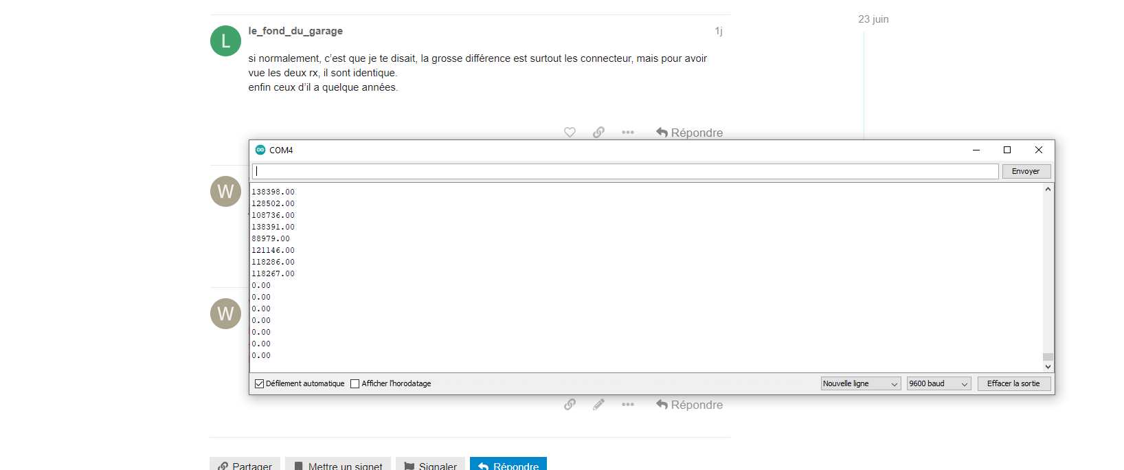
 mais non il y a pas de sortie ppm sur la vx2
 si tu connais qqun qui a déjà fait ça ?