peutr etre que ca peut jouer, mais je suis sur adruino nano
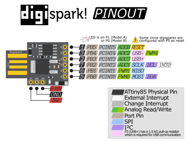
non, j’ai même réussi a l’installer sur un atiny85.
donc là c’est l’exemple fournie avec en plus.
bizarre.
tu a relancer ton pc des fois que?
Utilise celle de Solidgeek ou la mienne. Celle-ci est trop vieille.
Sinon c’est un projet que j’ai déjà fait il y a longtemps :

Le code par ici : GitHub - Peemouse/SmartRing: Battery gauge displaying VESC monitoring values
1 « J'aime »
oui oui mais rien n’y fais
Bon allé, j’ai claqué 15€ pour le contrôleur et la came périphérique, ch’uis un fou…
je vais essayer de faire fonctionner çà avec ma télécommande Maytech.
si tout se passe bien, je devrais pouvoir avoir des feux avant/arrière qui s’allument depuis la télécommande, et un feu stop qui sera piloté par le tiny85…
je commence le montage et je vous appelle au secours quand j’ai tout fait claquer 
1 « J'aime »
bon pour le moment je n’ai rien cramé, enfin si mais ce n’est pas lié au montage proposé mais plus à mon incapacité à reconnaitre un fil rouge et un fil noir…
j’ai donc monté mon banc de test.
le pb que je rencontre est avec le prog.
autant le dire dès maintenant, parce que çà va se voir… je suis total novice en prog.
quand je charge le prog proposé par Nenecossais, j’ai un message d’erreur de ma console qui me dit que:
‹ NEUTRAL_THROTTLE › was not declared in this scope
je vais me jeter dans le code, mais clairement si vous avez une idée de comment régler le pb… je suis preneur…
bon allé, j’ai trouvé la solution à mon problème précédant… j’ai recopier le code comme un con, il fallait juste faire du ménage…
mais ce qui est bon, c’est quand çà marche pas, et ouais, sinon on achèterait des trucs tout fait…
donc j’ai une question, est-ce que vous avez essayé de faire fonctionner ce montage avec un esc et pas un vesc?
mon banc de test est équipé d’un esc, j’avais çà en stock… et comme j’aime bien faire des tests avec du matos qui n’est pas celui que j’utilise au quotidien, je me suis dis que çà ferait l’affaire…
voici ce que j’observe, quand la broche P2 du tiny est connectée, l’impulsion ne passe plus jusqu’au contrôleur. Je n’ai pas non plus de réaction de la part de mon feu stop.
si je débroche P2… tout fonctionne (sauf le feu stop bien sur).
si vous aviez des pistes…
mes ton code, déja on y veras plus clair.
tu utilise un atiny85?
pense une fois le frequence et le type de changer a graver la séquence d’init. sinon cela ne marche pas.
pour infos voici mon code pour le atiny85, j’utilise un ruban led neo pixel pour l’avant et un autre pour l’arrière.
il est pas forcement super beau, mais il rentre dans le peu d’espace du micro.
"#include <Adafruit_NeoPixel.h>
#ifdef AVR
#include <avr/power.h>
#endif
#include <SoftwareSerial.h>
// Which pin on the Arduino is connected to the NeoPixels?
int ppm = 3;
int front = 1;
int back = 2;
// How many NeoPixels are attached to the Arduino?
int frontnumPixels = 7; // Popular NeoPixel ring size
int backnumPixels = 5; // Popular NeoPixel ring size
int brake;
int G;
int R;
int B;
int memppm;
unsigned long duration;
long memMillis;
int frontpos;
int frontdir;
int scan;
float smoothness_pts = 250;//larger=slower change in brightness
int ii;
float pwm_val;
float gamma = 0.14; // affects the width of peak (more or less darkness)
float beta = 0.5; // shifts the gaussian to be symmetric
Adafruit_NeoPixel frontled = Adafruit_NeoPixel(frontnumPixels, front, NEO_GRB + NEO_KHZ800);
Adafruit_NeoPixel backled = Adafruit_NeoPixel(backnumPixels, back, NEO_GRB + NEO_KHZ800);
void setup() {
frontled.begin();
frontled.setBrightness(255);
frontled.show(); // Initialize all pixels to ‹ off ›
backled.begin();
backled.setBrightness(255);
backled.show(); // Initialize all pixels to ‹ off ›
pinMode(ppm, INPUT);
memppm = pulseIn(ppm, HIGH); //je capture le neutre a l’allumage du module
//memppm=500;
ii=0;
}
void loop() {
//capture télécommande
duration = pulseIn(ppm, HIGH,33300);
//respiration
if(ii<smoothness_pts){ii++;}else{ii=0;}
pwm_val = 200*(exp(-(pow(((ii/smoothness_pts)-beta)/gamma,2.0))/2.0));
//asignement de valeur en fonction de la position de la télécommande
if (duration > memppm +100) {R=duration/10;G=duration/10;B=255;pwm_val=200;}else{R=50;G=50;B=50;}
if (duration < memppm -100) {brake=255;pwm_val=200;}else{brake=50;}
//les boucle ici en une fois pour réduire la taille mémoire
for(int i=0; i<frontled.numPixels(); i++) {frontled.setPixelColor(i, frontled.Color(R, G,B));}
for(int i=0; i<backled.numPixels(); i++) { backled.setPixelColor(i, backled.Color(brake, 0, 0));}
frontled.setBrightness(pwm_val+50);
frontled.show();
backled.setBrightness(pwm_val+50);
backled.show();
}
Salut,
merci pour ton aide.
mon code est celui proposé au début du post à savoir :
#define THROTTLE_SIGNAL_IN 0 // INTERRUPT 0 = DIGITAL PIN 2 - use the interrupt number in attachInterrupt
#define THROTTLE_SIGNAL_IN_PIN 2 // INTERRUPT 0 = DIGITAL PIN 2 - use the PIN number in digitalRead
#define NEUTRAL_THROTTLE 1500 // this is the duration in microseconds of neutral throttle on an electric RC Car
volatile int nThrottleIn = NEUTRAL_THROTTLE; // volatile, we set this in the Interrupt and read it in loop so it must be declared volatile
volatile unsigned long ulStartPeriod = 0; // set in the interrupt
volatile boolean bNewThrottleSignal = false; // set in the interrupt and read in the loop
// we could use nThrottleIn = 0 in loop instead of a separate variable, but using bNewThrottleSignal to indicate we have a new signal
// is clearer for this first example
void setup()
{
// tell the Arduino we want the function calcInput to be called whenever INT0 (digital pin 2) changes from HIGH to LOW or LOW to HIGH
// catching these changes will allow us to calculate how long the input pulse is
attachInterrupt(THROTTLE_SIGNAL_IN,calcInput,CHANGE);
Serial.begin(9600);
}
void loop()
{
// if a new throttle signal has been measured, lets print the value to serial, if not our code could carry on with some other processing
if(bNewThrottleSignal)
{
Serial.println(nThrottleIn);
// set this back to false when we have finished
// with nThrottleIn, while true, calcInput will not update
// nThrottleIn
bNewThrottleSignal = false;
}
// other processing …
}
void calcInput()
{
// if the pin is high, its the start of an interrupt
if(digitalRead(THROTTLE_SIGNAL_IN_PIN) == HIGH)
{
// get the time using micros - when our code gets really busy this will become inaccurate, but for the current application its
// easy to understand and works very well
ulStartPeriod = micros();
}
else
{
// if the pin is low, its the falling edge of the pulse so now we can calculate the pulse duration by subtracting the
// start time ulStartPeriod from the current time returned by micros()
if(ulStartPeriod && (bNewThrottleSignal == false))
{
nThrottleIn = (int)(micros() - ulStartPeriod);
ulStartPeriod = 0;
  // tell loop we have a new signal on the throttle channel
  // we will not update nThrottleIn until loop sets
  // bNewThrottleSignal back to false
  bNewThrottleSignal = true;
}
}
}
Bon j’ai pris mon temps mais j’ai enfin terminé mon système 
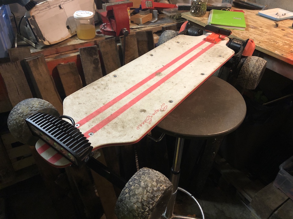
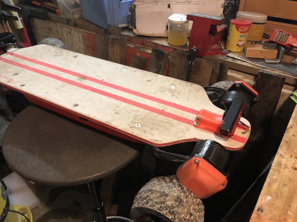
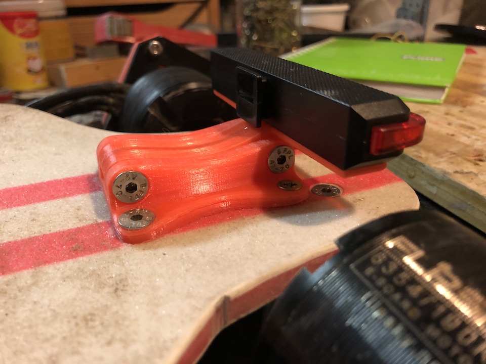
le feu arrière est allumé par l’inter principal et clignote quand je freine. j’aurai pu choisir une autre option mais voilà, il fallait faire un choix.
j’ai rajouté un phare à l’avant… peu être un peu puissant mais au moins je vois ce qu’il se passe quand je ride de nuit.
le phare avant est piloté par un relais présent sur le récepteur que j’utilise, je le pilote donc directement depuis la télécommande.
j’ai intégré l’ensemble du système sur une carte pcb avec un petit casing en impression 3D, la prochaine fois que j’ouvre la planche je vous fais des photos
Merci d’avoir ouvert ce post, je me suis bien amusé à bricoler ce système !
2 « J'aime »
c’est vraiment pas mal d’avoir des feux contrôlables à la remote ! GG
salut,
merci pour le partage.
je voudrais adapter ça de la sorte:
cela vous semble correcte ?
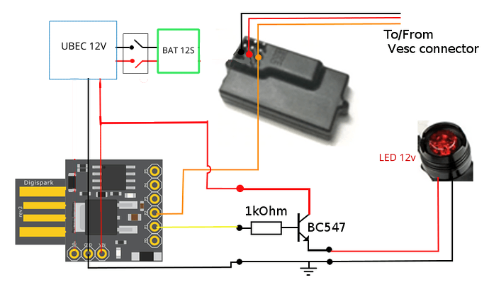
Le digispark est alimenté en 5v et non 12v… bref je pense pas que ça marche.en plus il faut le même potentiel de référence pour l’entrée signal…
c’est bien pour ca que je demande,
mais si je regarde çà, a priori çà fonctionne aussi en 12v